https://ift.tt/3A2GmKq Understanding in-phase and quadrature components using a phase modulation example I/Q data appears in many data sci...
Understanding in-phase and quadrature components using a phase modulation example
I/Q data appears in many data science settings: RF (radio frequency) data, timeseries analysis, audio processing, and more.
Plus, one of my favorite geometric demonstrations is the decomposition of an angle-modulated sinusoid into two orthogonal, amplitude-modulated sinusoids. As a teaser of what’s to come…
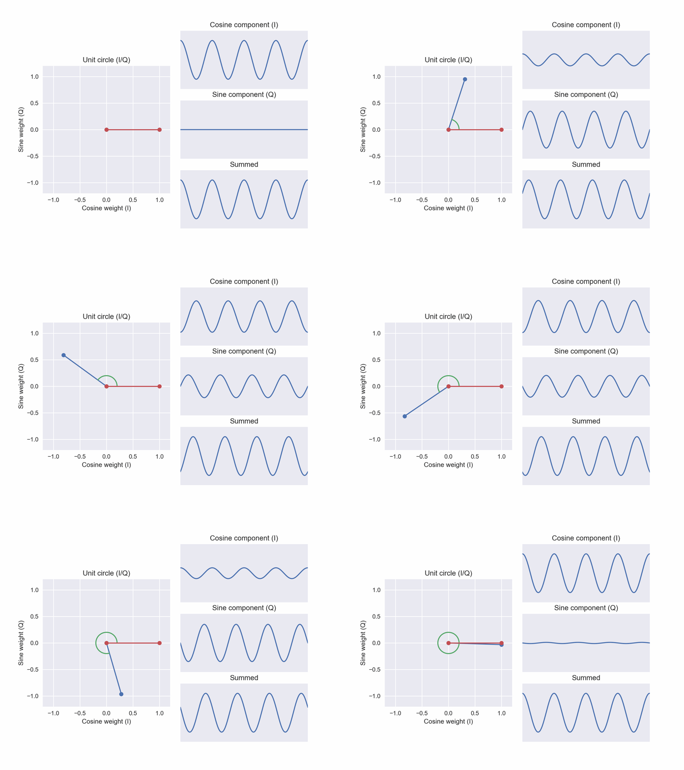
As a motivation, I’m going to use a radio example. From ham radio to radar imaging, I’m passionate about all things RF. In this article, we will explore how we can encode information in a wave using “phase shift keying” and how we can synthesize a wave of any desired phase using the sum of just two oscillators. Let’s dive in!
I created all graphics in this article. Feel free to reuse in any context without attribution (no rights reserved).

As discussed in greater depth in one of my other articles, “phase” describes the the left-to-right shift of a sinusoid. Given sinusoids of a specified frequency, the phase tells us the starting position of the oscillation in time or space. In Figure 1, I’ve plotted three identical sinusoids that differ only in phase. On the y-axis, I’ve also included the generating equations.
If you have your engineering hat on, you may be thinking “if I can change a thing, I can use it to encode information.” Indeed, you can! We can take a simple sinusoid (i.e., “carrier wave”) and modulate (i.e., change) the phase to communicate information to a receiver.
Binary phase-shift keying (BPSK)
BPSK is the simplest mechanism to communicate information by manipulating the phase of a carrier wave. The phase of a transmitted wave is changed between two states.
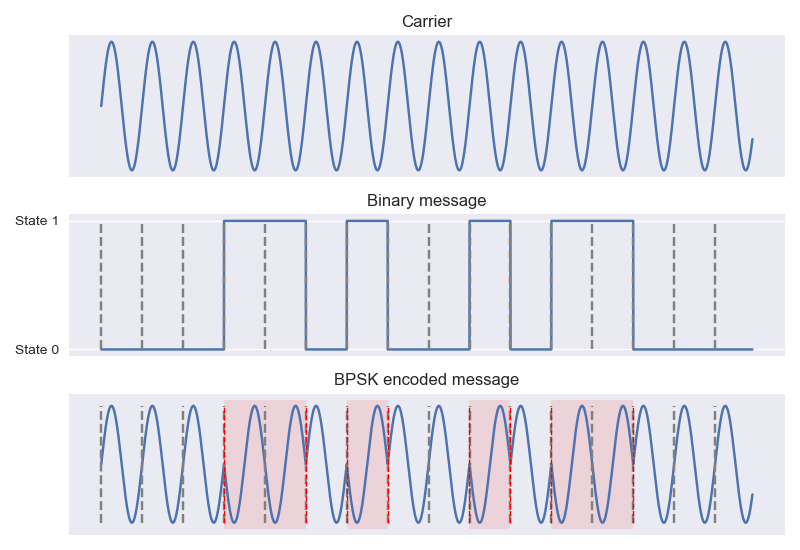
Piece of cake! Under BPSK, we can communicate two binary states. We just encode each state as a distinct phase. Typically, the two phase states are offset as much as possible from one another (180°). Above (Figure 2), I have encoded the sequence 0, 0, 0, 1, 1, 0, 1, 0, 0, 1, 0, 1, 1, 0, 0, 0 using the BPSK scheme.
Back to the engineering hat! If we can encode two states with two phase values, what if we used additional phases? What if we used four phase values to transmit one of four possible states per bit period to increase the information density of our transmission? We can! This extension is known as “quadrature phase shift keying” (QPSK).
This raises some practical questions, though… as we continue to introduce additional phase requirements, do we need to introduce additional oscillators?
Synthesis from in-phase and quadrature components
Instead, let’s think about how we might be able to create many sinusoids with different phases using a composition of simple building blocks.
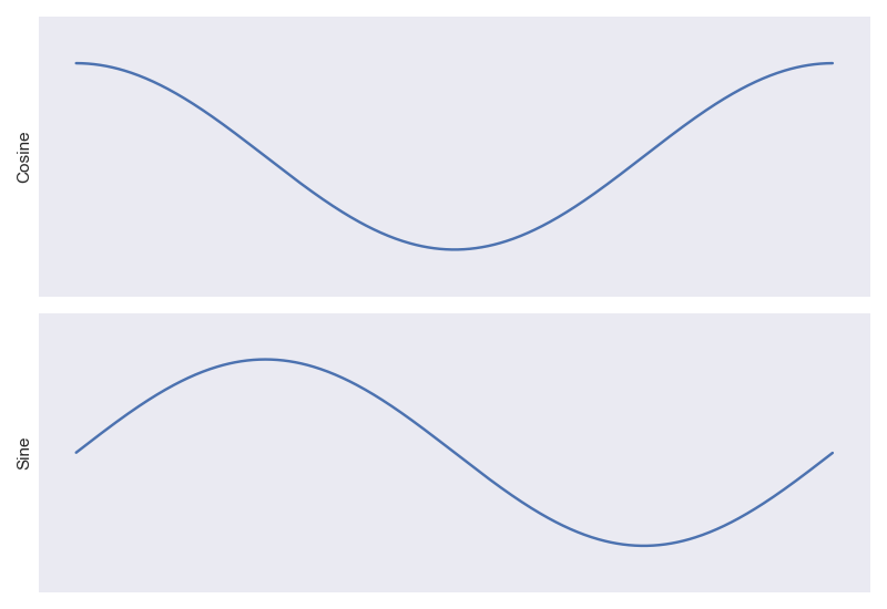
In my radio toolkit, I have lots of ways that I can generate a sine wave from a cosine wave. If I have an electronic oscillator that is generating a pure cosine, for instance, I can add a simple power and a delay line to generate a sine. Cosine and sine are just phase shifts of one another, offset by 90°. Generating one from the other is simple in hardware: I just need a time delay to shift the signal.
Now that I am working with both, though, it can be a little confusing to keep referring to them as “cosine” and “sine”. Since they are just phase shifts of one another, if I start measuring my signal at a random time point in the future, my “cosine” might look like a sine and my “sine” might look like a cosine! Instead, let’s use the cosine as a reference and call it “in phase.” We’ll call the sine our “quadrature” component. Excellent! I started with one phase and now I have two using only a power split and a tunable delay line.
My “in phase” and “quadrature” components seem to have some interesting properties. If I multiply my cosine signal and my sine and take the sum, I get zero. To say the same thing more formally, if I take the integral of the product of these two functions, my result is zero. This property is called “orthogonality.” They have a correlation of zero! This is excellent news, because it makes it easy to build a coordinate space. If I put my in-phase-iness on the x-axis and my quadrature-iness on the y-axis, I know that they are not correlated, so increasing along one axis doesn’t affect the value on the other.
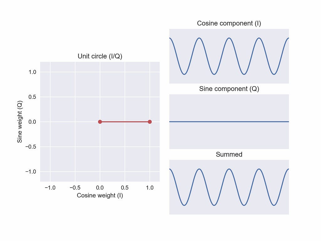
Let’s draw this in-phase-iness, quadrature-iness space. On the x-axis, we plot how much cosine we want (i.e., an “in-phase” weight on the cosine function). On the y-axis, we plot how much sine we want (i.e., a “quadrature” weight on the sine function). We can visualize the two weighted components and the weighted sum (Figure 4). We will call this new space I/Q to describe the two axes: (i)n phase and (q)uadrature
In blue, I’ve plotted the coordinate in-phase weight 1, quadrature weight 0 with a line to the origin. The distance to the origin is 1: √(1² + 0²). Unsurprisingly, when the sine weight is zero, our weighted sum is just the cosine!

Let’s move to the coordinate in-phase 0, quadrature weight 1 (Figure 5). This is a rotation of 90° from our previous position (red line). With an in-phase weight of zero, we just get our sine wave. We’re starting to see something interesting… a 90° rotation in this coordinate induces a 90° phase in our weighted sum. It was previously a cosine, now it is a sine. The geometry of our space encodes this property. Very cool!
We can also move to negative values on our axes. Effectively flipping (i.e. inverting) our cosine or sine component about the y-axis.
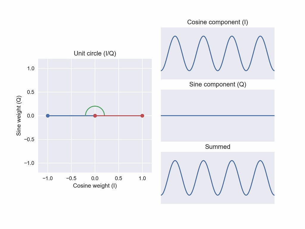
Jumping to the coordinate in-phase weight -1, quadrature weight 0 (Figure 6), we flip our original cosine component upside down! Again, if we look back to our original cosine reference, this flip is equivalent to a 180° phase offset from our first weighted sum. This also the first “new” phase we’ve constructed in this space. Using a mixture of our I and Q basis functions, we’ve built a sinusoid of a phase we didn’t have before.
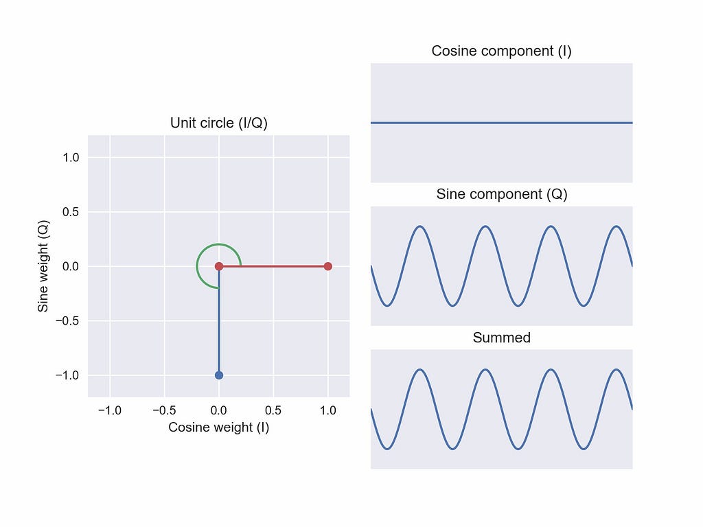
Finally, completing the spatial intuition, we invert our original sine function at the coordinate in-phase weight 0, quadrature weight -1 (Figure 7). This is our second “new” phase: a signal of a phase that we didn’t have before. Once again, the weighted sum is a 270° phase offset from the pure cosine we first examined. At each position we’ve seen, the angle (in green) has reflected the phase offset applied to the weighted sum.
As long as we can arbitrarily mix these two components, it seems like we can generate any phase we want! We’ll want to keep our distance to the origin constant (here, unit length) to make sure we aren’t changing the total power (i.e. magnitude, see some of my other articles for more context), but as we sweep over weights for the two components, we can synthesize a sinusoid of any phase we’d like. This is awesome! Starting with a single oscillator, adding a power split and a delay line, and now introducing a mixer, we can compose a sinusoid of any phase, leaving the frequency and the amplitude unchanged.
We have all the intuitions we need! Now we can revisit our original visualization.

If that isn’t a satisfying geometric result, I don’t know what is. It’s mesmerizing and useful. Next time you encounter I/Q values in the wild on a data science project, I hope they seem less intimidating!
If there are other concepts you’d like to see explained, leave a comment. Thanks for reading!
Mind your I’s and Q’s: The Basics of I/Q data was originally published in Towards Data Science on Medium, where people are continuing the conversation by highlighting and responding to this story.
from Towards Data Science - Medium https://ift.tt/33nPvRV
via RiYo Analytics

No comments